
How to control AC appliances with Microcontrollers like Arduino has always been a question for beginners. As you may know, Arduino works on a 5V logic level i.e. it can only control devices that operate on 5V. But what if you want to control devices/appliances that work on more than 5V like 24V or even 220V AC?
In this article, we will discuss about relays. How they work and how to use them to control high voltage devices. But first, if you are an absolute beginner then I recommend you to check out “Introduction to Arduino” to get familiar with Arduino.
Once you are familiar with that, we can now get started. Let’s first take a look at what a Relay is.
What is a Relay?
A relay functions as an electro-mechanical switch, enabling the control of high-power devices using low-power input. So using Relay we can control high-power appliances like Light bulbs or Motors using Microcontrollers like Arduino and ESP.
How does a Relay work?
The operation is quite simple, There is a coil which acts as an electromagnet. When powered this coil attracts a metal contact which toggles the switch position.
There are usually three contacts on an SPDT relay, normally open(NO), normally closed(NC) and common(COM)
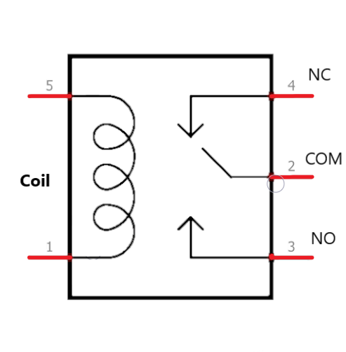
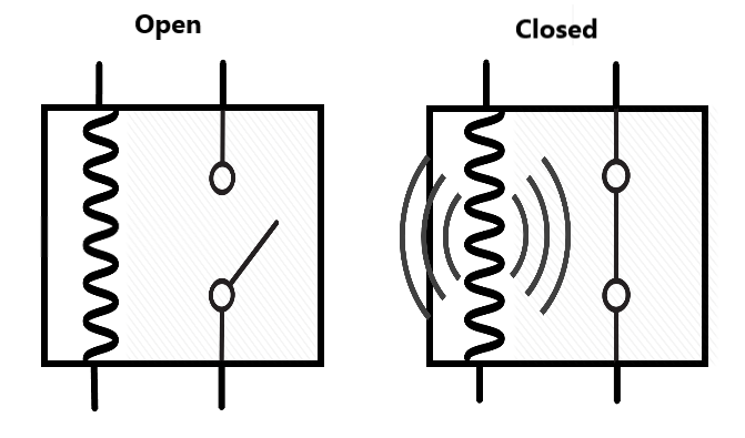
When the coil is powered on it attracts the contact which closes the Normally Open pin. A connection is made and the Appliance is turned on.
This allows one circuit (Lower powered) to switch on another circuit (Higher powered).
Using Relay Modules.
We can’t use a relay directly with Arduino. It needs a driver circuit for better working and protection of the microcontroller. This circuit usually consists of a reverse protection diode, a transistor, couple of resistors and an opto-coupler for isolation.
We can build this circuit on a breadboard or Perf board but there are Relay modules available for cheap which are better made and easy to use. These modules can be in 1ch, 2ch, 4ch up to 16ch boards. Here ‘ch’ means Channel or number of relays on the board.
Requirements:
Here is a list of all the materials we will need for controlling an AC appliance using Arduino.
| Arduino Nano | Amazon US | Amazon IN | Banggood |
| Relay Module | Amazon US | Amazon IN | Banggood |
| Breadboard and Jumpers | Amazon US | Amazon IN | Banggood |
After gathering these components we can move on and start making connections.
Connections:
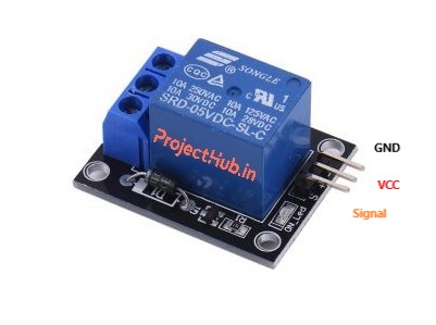
For this test, I have used a 4ch relay module. But you can use any number of relays. All relays have similar pinouts: VCC, GND and Inputs.
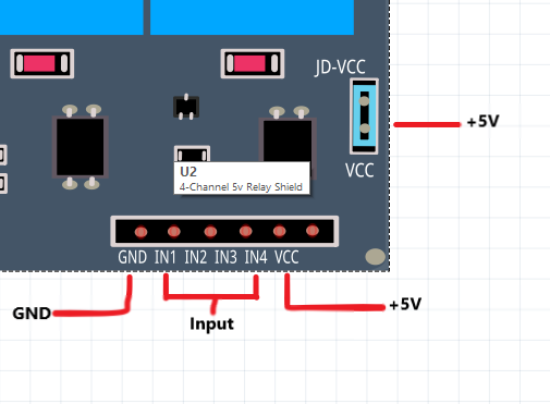
As labelled in the image above, first there is GND. Which connects to the GND of Arduino or any microcontroller. This is very important I have seen people not connecting the grounds in a circuit and then ask why the circuit does not work.
The four pins labelled IN1, IN2, IN3, and IN4 function as input pins and will be connected to the digital pins of the Arduino. These pins operate at a 5V logic level.
The last pin is VCC, this is the +5V pin that powers the board. On a multiple channel relay, you will always see another set of VCC pins usually to the right. These are the pins used to power the relays. I recommend powering it with a separate 5V supply if you have a 4ch or higher board.
Now let’s make the connections:
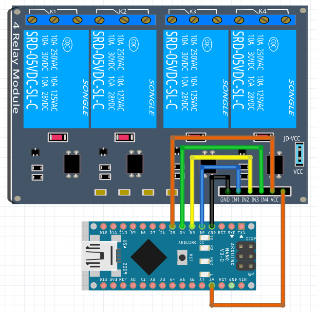
The connections between the relay module and the Arduino Nano V3.0 in the above diagram are quite straightforward.
- VCC >> +5V (The relays are powered by Arduino directly but if you have a module with more than 4ch, use a separate power supply)
- GND >> GND (If using an external power supply, connect its GND to Arduino to make a common ground.)
- IN1 >> D2
- IN2 >> D3
- IN3 >> D4
- IN4 >> D5
That’s all the connections, now we can write a simple code to to toggle on the relays.
Programming:
For testing this setup we don’t need a complex code. Below is a simple code that will test the relay modules and make sure our setup works.
#define IN1 D2
#define IN2 D3
#define IN3 D4
#define IN4 D5

Void setup()
{
  pinMode(IN1, OUTPUT);
  pinMode(IN2, OUTPUT);
  pinMode(IN3, OUTPUT);
  pinMode(IN4, OUTPUT);

  digitalWrite(IN1, LOW);
  digitalWrite(IN1, LOW);
  digitalWrite(IN1, LOW);
  digitalWrite(IN1, LOW);
}

void loop()
{
  digitalWrite(IN1, HIGH);
  delay(500);
  digitalWrite(IN2, HIGH);
  delay(500);
  digitalWrite(IN3, HIGH);
  delay(500);
  digitalWrite(IN4, HIGH);
  delay(3000);
  digitalWrite(IN1, LOW);
  delay(500);
  digitalWrite(IN2, LOW);
  delay(500);
  digitalWrite(IN3, LOW);
  delay(500);
  digitalWrite(IN4, LOW);
  delay(2000);
}
What this code will do is turn on each relay one by one then stay on for 2 seconds and then turn off the relays one by one again. This is just to test the setup.
Final Note:
This post served as an introduction to relays and their control with Arduino. In future projects, we’ll leverage this understanding to create exciting endeavours, such as home automation and beyond.
If you have any questions or doubts feel free to ask in the comment section.
Hope this post was informative and you learnt something new. If you did, make sure to subscribe to stay updated with the latest tutorials and posts.