
It takes a lot of components along side the microcontroller itself to make a robot. There are Motor Drivers, Servo Controllers and voltage regulators. To connect all these components we need breadboard or perf board to solder everything together. This may take a considerable amount of time and makes a mess with wires. This makes it hard for people to dbug the connections if something goes wrong.
To avoid this problem, Robot Controllers are used. Robot controllers are compact boards with most of the important components and Pins one will need to make a robot. There are many Robot controllers in the market and the one we are going to use here is a little different. This particular board is called “Nano Robot Controller”
it is designed by me and manufactured by BPI factory.
In this article we shall see what a robot controller is, what is it used for and how to get started with the Nano Robot controller.
Components:
Disclaimer: This blog contains Amazon and Aliexpress Affiliate links. Buying product from those links helps us run this blog without any extra charges on you.
- BPI Nano. (Currently only available on Aliexpress)
- Nano Robot Board. (Currently only available on Aliexpress)
- 2WD Robot Chassis. (Amazon/Aliexpress)
I have used the chassis of KeyBot for this project. You can also build a chassis yourself, here is an e-book that will teach you in details: Mini WiFi Robot.
What is a Robot Controller?
The first question one might ask is, What really is a robot controller?
In short term, robot controller is nothing but a PCB with components you might need to build a fully functioning robot. There are different types of robot controllers ranging from $10 all the way up to $500. Most cheap ones are in the form of a shields for Arduino or Raspberry Pi. Which has Motor driver and other ICs soldered on and it just snaps on to the headers of the Arduino or Pi.
Robot controllers usually have motor drivers and PWM controllers on board along with some GPIOs where you can hook up different peripherals and sensors. Some might even have a microcontroller on board eliminating the need of Arduino.
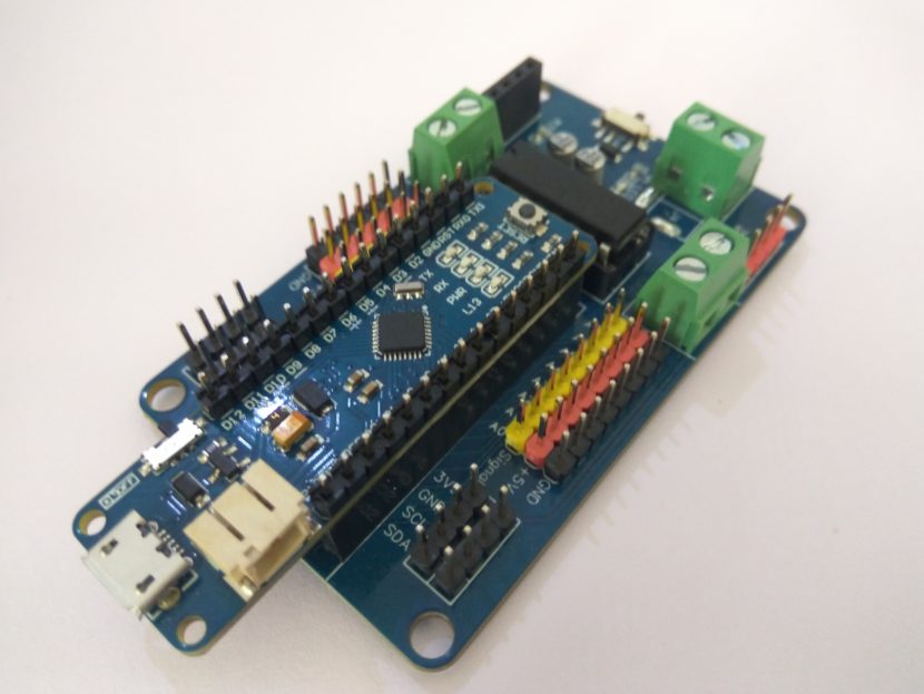
The Robot controller we are going to learn about today is called Nano Robot Controller which is a compact board designed to work with Arduino Nano and Nano compatible boards. Lets see the board in more details.
Nano Robot Controller Board:
Nano Robot Controller is a compact board consisting of all the basic components you will need along with GPIO to add sensors. Below are the hardware specifications you must know before using the board.
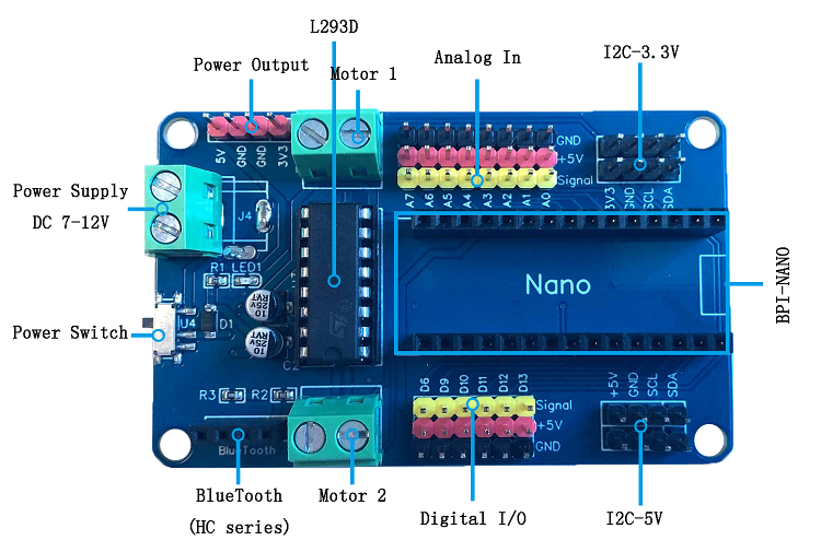
- L293D dual H-bridge motor driver. It can control 2 DC motors speed and direction independently.
- Analog pins: Which can be used to hook-up multiple sensors like IR, Ultrasonic, and more.
- Digital pins: Six pins, out of which four are PWM enabled (D6, D9, D10, D11).
- I2C: There are two sets of I2C pins one is 3.3V and other is 5V. These pins allow I2C communication with other devices and sensors.
- Bluetooth: HC-05 or HC-06 can be connected to add wireless control.
- Logical working voltage: 5V DC.
- Motor drive voltage: 7v-12v DC.
- Maximum driving current: 1A
- Size: 75mm x 45mm (2.9″ x 1.7″)
Pin Configuration for Motor Controller:
- D3 = ENA
- D5 = ENB
Where ENA controls the speed of Motor 1 and ENB controls the speed of Motor 2.
- IN1 = D2
- IN2 = D4
- IN3 = D7
- IN4 = D8
Where D2, D4 controls the direction of “Motor 1” and D7, D8 controls the direction of “Motor 2”.
The I2C pins are connected to A4 and A5. Where SDA is A4 and SDL is A5.
All the other pins are marked on the board itself. The board also has Bluetooth connector which is connected serially to the Nano i.e TX and RX. Here TX is D1 and RX is D0.
Now that we are familiar with the Robot Control Board, we can start making our first project with it.
Building a Simple Robot:
Now that we have a better understanding of what a Robot Controller is and the necessary pinouts, we can start building our first robot.
We will need a chassis first. I have reused the chassis from KeyBot as it is a very well built frame. For adding the Robot board I mounted a peace of hard foam board on 4 pillars and mounted the board on top with 4 standoffs.
You can refer to the image bellow for better understanding.
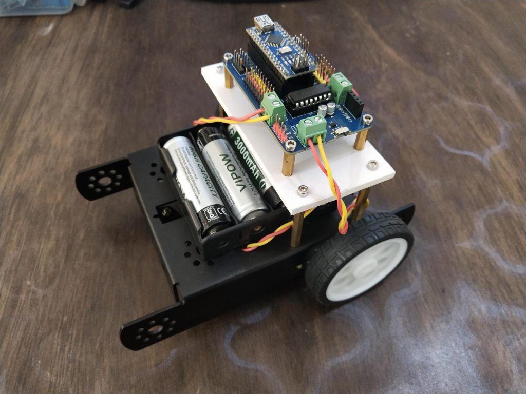
Once we have a chassis ready with the board secured on top, we can start connecting the wires. Follow the instructions below:
- First connect the Left motor to “Motor 2” terminal.
- Next connect the Right motor to “Motor 1” terminal.
- Finally connect the battery to the power terminal.
Note that the power terminal is not labeled. The screw connector closest to the mounting hole is Positive.
Other way you can check the pin is by using continuity checker of a multimeter. Just touch one lead to any GND pin on the board and connect other lead of multimeter to each terminals of the Power block. The multimeter will beep when the connection is completed and that is the GND or negative terminal.
Use 7V-12V battery pack to power the robot.
Programming:
Finally we need to write a code and upload it to the nano which will bring our robot to life. To program the robot first make sure you have Arduino IDE installed on your computer, if not then download and install the latest version from here.
Now let’s start writing the code.
int ENA = 3;
int ENB = 5;
int IN1 = 2;
int IN2 = 4;
int IN3 = 7;
int IN4 = 8;
First we declare the required variables. These will control our motor driver. ENA and ENB are PWM pins which will help use control the speed of our robot. IN pins control the direction in which motors will turn.
void setup()
{
  Serial.begin(9600);
  pinMode(ENA, OUTPUT);
  pinMode(ENB, OUTPUT);
  pinMode(IN1, OUTPUT);
  pinMode(IN2, OUTPUT);
  pinMode(IN3, OUTPUT);
  pinMode(IN4, OUTPUT);
}
Setup function will be the first function to execute in a code. Here we will set the mode of each pin.
First I like to include the serial functionality to debug but it is optional. All the pins are set as outputs as we are not connecting any sensor to our robot in this project.
Next we will write movement functions, this will make the code a lot easier to understand and modify.
We need five movement functions in general, Forward, Backward, Left and Right.
void front()
{
  Serial.println("FORWARD");
  analogWrite(ENA, 75); //PWM 0-255
  analogWrite(ENB, 75); //PWM 0-255
  digitalWrite(IN1, HIGH);
  digitalWrite(IN2, LOW);
  digitalWrite(IN3, HIGH);
  digitalWrite(IN4, LOW);
}
Here also I have used the serial print to print the action on serial monitor.
The ENA and ENB pins both are set to 75. Notice here I have used “analogWrite” function which will set the speed of our motor. To lower or increase the speed you can lower or increase the value anywhere between 0-255, where 0 will stop the motor and 255 will run it in full speed.
For going forward we want both the motors to move in same direction at the same speed. We set the speed to 75. Also we set the pins IN1 and IN3 to HIGH. This will make both the motors to move in same direction.
void left()
{
  Serial.println("LEFT");
  analogWrite(ENA, 50);
  analogWrite(ENB, 50);
  digitalWrite(IN1, LOW);
  digitalWrite(IN2, LOW);
  digitalWrite(IN3, HIGH);
  digitalWrite(IN4, LOW);
}
The above code is pretty similar to the last one. Here only one pin IN3 is high, this will just make ‘Motor 1’ run forward at the speed of 50. This will cause the robot to turn Left.
void right()
{
  Serial.println("RIGHT");
  analogWrite(ENA, 50);
  analogWrite(ENB, 50);
  digitalWrite(IN1, HIGH);
  digitalWrite(IN2, LOW);
  digitalWrite(IN3, LOW);
  digitalWrite(IN4, LOW);
}
Here IN1 is high which will make ‘Motor 2’ run forward at speed of 50. This will cause the robot to turn Right.
void back()
{
  Serial.println("BACKWARD");
  analogWrite(ENA, 75);
  analogWrite(ENB, 75);
  digitalWrite(IN1, LOW);
  digitalWrite(IN2, HIGH);
  digitalWrite(IN3, LOW);
  digitalWrite(IN4, HIGH);
}
This function is just opposite of the first function ‘front()’. Here the pins IN2 and IN4 are High, this will make both the motors run backwards.
void stops()
{
  Serial.println("STOP");
  analogWrite(ENA, 0);
  analogWrite(ENB, 0);
  digitalWrite(IN1, LOW);
  digitalWrite(IN2, LOW);
  digitalWrite(IN3, LOW);
  digitalWrite(IN4, LOW);
}
This function will stop both the motors, as you can notice all the pins are set as Low and the ENA , ENB pins are also set as 0.
Finally we need the loop function which will carry out particular actions in a loop until the board is powered off or reset.
void loop()
{
  front();
  delay(1000);
  left();
  delay(1000);
  front();
  delay(1000);
  right();
  delay(1000);
  front();
  delay(1000);
  stops();
  delay(1000);
  back();
  delay(1000);
}
Here as you can see, we will just call all the functions and loop will run them one by one from top to bottom.
I have also added a second of delay after every function.
Now we can upload this code onto the Microcontroller. In this case BPI Nano using the IDE.
Final Note:
Now all we have to do is power up the board and watch the Robot perform the maneuvers as codded in the loop function. You can interchange the movement functions to achieve different results.
This was just a basic tutorial to introduce you to the Nano Robot Board. In future we will make different robots and explore all the other features the board offers, so make sure you subscribe for updates.
One thought on “Nano Robot Controller Board”