

Are you a beginner and want to get into robotics? Then you must have many questions in mind like “How to make the robot move?” or “Which tools to use to make the robot move?”. If you are anything like me then you probably have disassembled tons of toys to figure that out. The most common thing you find in these toys is DC motors.
In this tutorial, we will see, how to control a DC Motor, its speed and direction using Arduino and L293D motor driver IC. So without wasting any more time, let’s get right into it.
Disclaimer: This blog contains Amazon Affiliate links. Buying products from those links helps us run this blog without any charges on you.
Requirements:
For this project, we will need:
| Arduino UNO | Amazon Global | Amazon.in | Aliexpress |
| L293D IC | Amazon Global | Amazon.in | Aliexpress |
| Breadboard Kit | Amazon Global | Amazon.in | Aliexpress |
| DC Motor | Amazon Global | Amazon.in | Aliexpress |
What Is L293D?
So everything in the list might look familiar except “L293D“. Let me explain about this IC in a simple and short term. L293D is a motor drive IC which can be used to control 2 DC motors or 1 Stepper motor. It has 2 H-bridges which help control the speed and direction of motors.
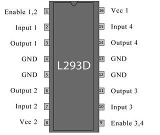
We cannot connect a motor directly to Arduino as it will fry the board instantly. So we use a motor driver like L293D or L298N. You can find motor driver modules and shields online which help control multiple motors but for this tutorial, we will stick with minimum for learning the basics.
In the above image, you can see the pinouts of the IC. Each side controls one motor. For this tutorial, we will control only one motor using Arduino. Below is a breakdown of the pins of L293D.
| Pin No | Function | Name |
| 1 | Enable pin for Motor 1 | Enable 1,2 |
| 2 | Input 1 for Motor 1 | Input 1 |
| 3 | Output 1 for Motor 1 | Output 1 |
| 4 | Ground | Ground |
| 5 | Ground | Ground |
| 6 | Output 2 for Motor 1 | Output 2 |
| 7 | Input 2 for Motor 1 | Input 2 |
| 8 | Power the Motors | Vcc 2 |
| 9 | Enable pin for Motor 2 | Enable 3,4 |
| 10 | Input 1 for Motor 1 | Input 3 |
| 11 | Output 1 for Motor 1 | Output 3 |
| 12 | Ground | Ground |
| 13 | Ground | Ground |
| 14 | Output 2 for Motor 1 | Output 4 |
| 15 | Input2 for Motor 1 | Input 4 |
| 16 | Power the IC | Vcc 1 |
Connections:
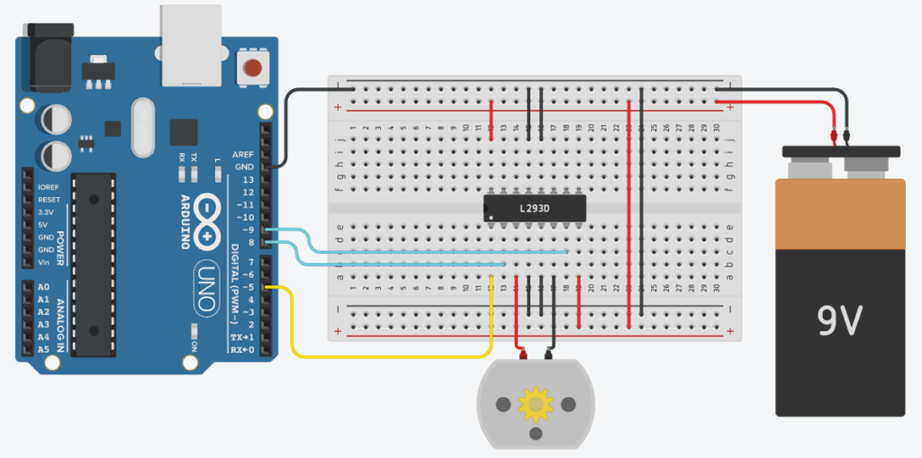
Here we have connected the input pins of the IC to Arduino:
- IN1 to Pin 8
- IN2 to Pin 9
- Enable1 to Pin 5 (PWM)
Pin 4,5,12,13 of the IC is connected to the GND of Arduino and battery. If you don’t do this, the motor will not work. Connect Pin 8 and 16 of the IC to the +ve terminal of the 9v battery. This will power our motor and the IC itself. That’s all we need to do. now we can write code to control the motor.
Coding:
First, we define the pins that we will be using.
#define ENA1 5
#define IN1 8
#define IN2 9
Here the ENA1 pin is connected to pin 5 of Arduino as it is a PWM-enabled pin. This will help us control the speed of our motor.
Next, there are pins 8 and 9 connected to pins IN1 and IN2 respectively. These pins will make the motor start, stop and change direction depending on which pin is HIGH/LOW.
void setup()
{
   pinMode(ENA1, OUTPUT);
   pinMode(IN1, OUTPUT);
   pinMode(IN2, OUTPUT);
}
In the setup we set the purpose of the declared pins, in this case, all pins are set as output.
Now comes the loop function. The code in this part runs in a loop.
void loop()
{
   analogWrite(ENA1, 255); //Sets speed of motor using PWM

   digitalWrite(IN1, HIGH); //Input 1 is turned on

   digitalWrite(IN2, LOW); //Input 2 is turned off

   delay(3*1000); //Runs for 3 seconds


   analogWrite(ENA1, 255);

   digitalWrite(IN1, LOW); //Both inputs are turned off

   digitalWrite(IN2, LOW);

   delay(2*1000); // Waits for 2 seconds


   analogWrite(ENA1, 255);

   digitalWrite(IN1, LOW); // Input 1 is off

   digitalWrite(IN2, HIGH); // Input 2 is on

   delay(3*1000); //Runs for 3 seconds


   analogWrite(ENA1, 255);

   digitalWrite(IN1, LOW);

   digitalWrite(IN2, LOW);

   delay(2*1000);
}
Here notice the function analogWrite(ENA1, 255) we are using the PWM feature of pin 5. The PWM value can be anything between 0-255, where 0 will turn off the motor and 255 will spin the motor at full speed. Varying the value between 1-254 will give different speeds.
The next two functions are digitalWrite, which sets a pin either HIGH or LOW. As in the above example, the IN1 is HIGH and IN2 is LOW, this will make the motor turn in one direction. Right or Left depending on the way you connected the terminals.
Swapping the HIGH and LOW will change the direction of rotation, and making both LOW/HIGH Will make the motor stop.
Now that you have an idea of the code, it’s time to upload the code. So connect your Arduino to your PC and upload the code.
Testing:
Now that the code is uploaded, power the motors and IC with 9v as shown in the circuit in the previous step. You will see that the motor spins in one direction for 3 seconds then stops for 2 seconds and spins in another direction.
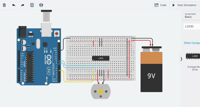
Here you can see the code in action. Now you can edit the code and change the values in analogWrite. Make it anything between 0-255 and see the results. Similarly, you can control one more motor with L293D.
That’s all for this tutorial. Now you know how to control DC motors using Arduino. There are other better methods like using Motor drive modules and shields but that’s a topic for another tutorial. Till then keep experimenting. Also, check out “Introduction to Arduino” if you are not already familiar.
Feel free to ask any doubts or leave any suggestions. If you liked the tutorial, follow for more. It’s totally free!
4 thoughts on “How to Control DC Motor Using Arduino”
i am a bigner .could you help me how i can start?
Check the blogs posted previously and follow for more content.
If you have any questions regarding any tutorials, feel free to comment.