
In previous tutorials, we learnt “How to use a pushbutton with Arduino” and “How to control a DC motor with Arduino“. In this article, we will see how to control Servo Motors. Servo motors are very useful in many projects, mostly robotic. Before we can control one we have to know what a Servo motor is and how it works.
Disclaimer: This blog contains Amazon Affiliate links. Buying products from those links helps us run this blog without any charges on you.
Introduction To Servo Motor:
In the market, various types of servo motors exist, offered in diverse form factors. However, they all operate similarly. Unlike a DC motor, which rotates 360°, a servo motor travels only 180° and incorporates a gear system to enhance torque.
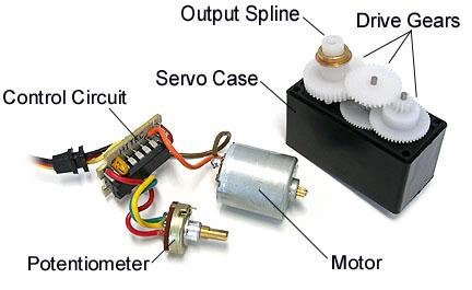
The image above reveals the internals of a standard hobby servo. It comprises three essential parts: the motor, control circuit, and drive gears, all enclosed in a case. Operating as a closed-loop motor controller, the circuit includes a feedback potentiometer. This potentiometer sends feedback to the circuit, indicating the current position of the servo shaft.
Pinouts:
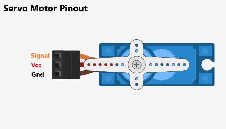
In the image, you’ll notice that the servo features 3 pins: Signal, Vcc, and GND. These pins are distinguishable by the colour of the wires. Typically, the signal wire is Orange or Yellow, the Vcc wire is Red, and the GND wire is Black or Brown.
Now that you’re familiar with the servo’s pins, let’s proceed to learn how to control a servo using Arduino. Before diving in, here are some items you’ll need.
Requirement:
| Arduino UNO | Amazon Global | Amazon IN | Aliexpress |
| 9G Servo | Amazon Global | Amazon IN | Aliexpress |
| 10K Potentiometer | Amazon Global | Amazon IN | Aliexpress |
Now that we have gathered all the required components, we can move forward to control the servo.
Controlling Servo Using Arduino:
To control a servo, we require PWM signals. PWM, which stands for Pulse Width Modulation, involves using a digital pin to generate a square wave. This signal comprises alternating high and low pulses with equal time intervals. The duration of the high signal, known as Pulse Width, can be adjusted to create different frequencies.
These frequencies determine the angle of the servo horn.
Arduino UNO provides 6 PWM pins (3, 5, 6, 9, 10, & 11). Since UNO is an 8-bit controller, its PWM ranges from 0 to 255, with 0 representing the lowest value and 255 the highest.
To control the Servo we will use this feature of the Arduino. So let’s start with something simple.
1. Simple Servo Control With Arduino:
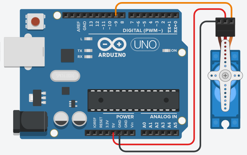
Begin by connecting the servo to the Arduino as illustrated in the figure. Connect the Vcc to 5V, GND to GND, and the Signal pin to pin 9. The servo is powered directly from the Arduino, but if you intend to use multiple servos, I recommend utilizing an external power supply. For detailed power requirements of your servo, refer to its datasheet.
Now refer to the code below:
#include Servo.h; //import the servo library

Servo myServo; //set servo variable as myServo

void setup()
{
   myServo.attach(9); //connect servo signal to pin 9
}

void loop()
{
   for(int i=0; i <= 180; i++) //goes 0 to 180 real quick ;p
   {
      myServo.write(i); //writes the value to turn servo
      delay(50); //50ms delay
   }

   for(int i=0; i >= 0; i--) //goes form 180 to 0
   {
      myServo.write(i); //writes the value to turn servo
      delay(50); //50ms delay
   }
}
Upload this code to uno. You will notice the servo sweeps from end to end.
This code is best for checking if a servo is working. But for most projects, we need a precise way to control the servo angle. For that, we will use a potentiometer.
2. Controlling Servo Using Potentiometer:
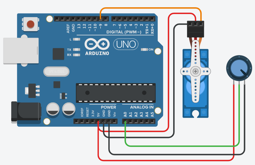
In this circuit, the servo connections remain the same as before. Additionally, we’ve incorporated a 10k ohm potentiometer (variable resistor). The central terminal of the potentiometer is connected to pin A0, while the other two terminals are linked to 5V and GND. By adjusting the resistance of the potentiometer, analogue values are generated and mapped to control the servo. This enables precise control over the servo’s movement, leveraging the change in resistance of the potentiometer.
Let’s take a look at the code:
#include<Servo.h>

Servo myServo;
int potPin = 0; //Set a variable named potPin as A0

void setup()
{
  myServo.attach(9);
}

void loop()
{
  int val = analogRead(potPin); // read the pot value,save it in val
  val = map(val, 0, 1023, 0, 180); //scale the pot readings to 0-180
  myServo.write(val); //set the servo position according to val
  delay(50); //50ms delay
}
Upload the provided code to the Arduino, and you’ll observe the servo moving to a specific position, determined by the potentiometer’s position. As you turn the potentiometer, the servo head will move accordingly.
The above method combined with other projects can be used for many applications like RC toys, robots and much more. We will see some projects related to it in future.
That’s all for this tutorial. If you have any doubts or questions, feel free to ask in the comments. If you like my tutorials do follow for more.
One thought on “How To Control Servo Motor Using Arduino”