
Previously, we explored the RoMeo BLE robot controller by DFRobot. In this tutorial, we’ll build a robot using the RoMeo BLE. This hands-on project will help you discover more features of the controller and learn how to utilize it effectively.
Requirements:
| RoMeo BLE | DFRobot | |
| 2WD MiniQ | DFRobot | |
| 18650 2 Cell Holder | Amazon | |
| 18650 Cells | Amazon | |
| Standoffs M3*60 (or you can use M3*50 + M3*10) | Amazon | |
| M3 Screws & Nuts | Amazon |
You will also need a few tools, such as a screwdriver and needle-nose pliers, to assemble the miniQ chassis.
Assembling the miniQ 2WD Robot Chassis:
Here’s what we get in the box:
- Base Plate
- 2 x Caster wheels
- 2 x N20 6V Geared Motors
- 2 x N20 Motor mounts
- Screw set
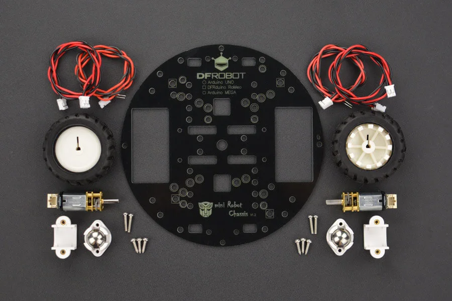
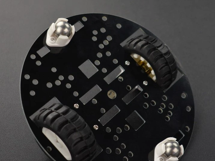
Start by ensuring you have all the materials ready. Attach the wheels to the motors, applying enough force to ensure they fit snugly onto the motor shafts. A loose fit can prevent the wheels from aligning properly with the slots on the chassis. Once the wheels are securely attached, fix the motors and caster wheels onto the baseboard using the provided screws. After assembly, your setup should resemble the image below.
Assemble the RoMeo BLE Robot Controller:
I urge you to check out the article “Robot controller Board : RoMeo BLE” if you haven’t already. It covers all the essential details you need to know about the RoMeo BLE board.
Now that you have understood the RoMeo BLE board and assembled the miniQ chassis, the next step is to combine both. First, connect 4 standoffs to the 4 mounting holes on the robot controller board. After that, align the standoffs with the mounting holes on the base plate and fasten them with nuts to secure them. Make sure to use 60mm tall standoffs, as I tried with 50mm and there was no space on the bottom to place the battery pack.
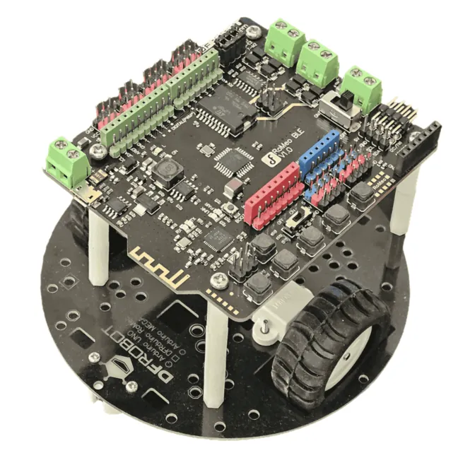
After assembling the board, your setup should look like the image above. Next, you need to make the connections. The connections are simple and straightforward—just follow the given instructions.
- With the motors, you’ll receive two types of wires. One has a JST connector on both ends, while the other has a JST connector on one side and open ends on the other. Use the second type, as it connects to the screw terminals on the RoMeo BLE board.
- Connect the wires to the motor contacts, then insert the open ends into the motor terminals labelled M1 and M2 on the RoMeo BLE board. Pay close attention to the labels next to the terminals: connect the red wire to + and the black wire to –. Ensuring correct motor polarity is crucial for proper operation.
- To power the motors, connect an external battery. Attach the red wire from the battery holder to the M_VIN terminal and the black wire to the GND terminal on the RoMeo BLE board.
After completing the connections, it’s time to move on to the coding part. If you’re new to controlling motors with Arduino, I recommend checking out “How to Control DC Motors with Arduino“ and “Everything You Need to Know About Motor Drivers“ for detailed guidance.
Writing the Code:
Now that the hardware setup is complete, it’s time to write a simple code to get things running. If you’re already familiar with Arduino programming, this should be straightforward.
Install & Setup Arduino IDE:
First, visit Arduino.cc and download the latest Arduino IDE for your operating system. If you’re using Windows, install the Windows version, as I have already done. Next, follow the steps as shown below:
- Connect the RoMeo BLE board to the computer using a micro USB cable.
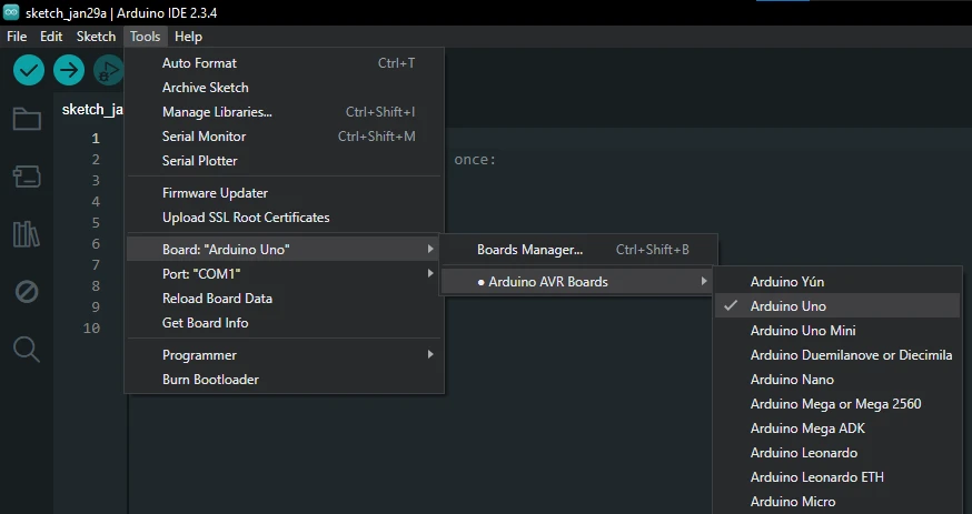
- Open the Arduino IDE. On the top left side, you’ll see a list of options. Click on “Tools”.
- From the drop-down list, select “Board”
- From the options select “Arduino AVR Boards”
- Next, You will see a list of boards from which you need to select “Arduino UNO”
- Notice the “Port” option right below “Board”. Select the available COM port—mine is COM1. If multiple ports appear, disconnect the board and check which one disappears. That’s your correct COM port.
Coding:
Now, let’s look at a simple code to control the motors using keyboard inputs via the Serial Monitor. This will help you understand how the board works and how to use the motor drivers effectively.
Note the pin functions :
| Digital Pins | Functions |
| D4 | Motor 1 Direction Control |
| D5 | Motor 1 PWM Contorl |
| D6 | Motor 2 PWM Control |
| D7 | Motor 2 Direction Control |
int E1 = 5;     //M1 Speed Control
int E2 = 6;     //M2 Speed Control
int M1 = 4;    //M1 Direction Control
int M2 = 7;    //M1 Direction Control

void stop(void)                    //Stop
{
  digitalWrite(E1,LOW);
  digitalWrite(E2,LOW);
}

void advance(char a,char b)          //Move forward
{
  analogWrite (E1,a);      //PWM Speed Control
  digitalWrite(M1,HIGH);
  analogWrite (E2,b);
  digitalWrite(M2,HIGH);
}

void back_off (char a,char b)          //Move backward
{
  analogWrite (E1,a);
  digitalWrite(M1,LOW);
  analogWrite (E2,b);
  digitalWrite(M2,LOW);
}

void turn_L (char a,char b)             //Turn Left
{
  analogWrite (E1,a);
  digitalWrite(M1,LOW);
  analogWrite (E2,b);
  digitalWrite(M2,HIGH);
}

void turn_R (char a,char b)             //Turn Right
{
  analogWrite (E1,a);
  digitalWrite(M1,HIGH);
  analogWrite (E2,b);
  digitalWrite(M2,LOW);
}

void setup(void)
{
  int i;
  for(i=4;i<=7;i++)
    pinMode(i, OUTPUT);
  Serial.begin(115200);      //Set Baud Rate
  Serial.println("keyboard control");
}

void loop(void)
{
  if(Serial.available()){
    char val = Serial.read();
    if(val != -1)
    {
      switch(val)
      {
      case 'w'://Move Forward
        advance (255,255);   //move forward in max speed
        break;
      case 's'://Move Backward
        back_off (255,255);   //move back in max speed
        break;
      case 'a'://Turn Left
        turn_L (100,100);
        break;
      case 'd'://Turn Right
        turn_R (100,100);
        break;
      case 'x':
        stop();
        break;
      }
    }
    else stop();
  }
}
Copy the code above and paste it into the Arduino IDE. Then, ensure you have selected the correct board and COM port. To upload the code, click on the upload button at the top left, represented by a right-pointing arrow.
After successfully uploading the code, power the board using a 7.4V battery. Remember, the board won’t turn on unless you toggle the slide switch next to the Motor power terminal to ON.
To test if the code and connections are working, elevate the robot or hold it up so the wheels don’t touch the surface—this prevents it from running off while still connected to the computer.
Next, open the Serial Monitor using one of the following methods:
- Goto > Tools > Select Serial Monitor
- Use the shortcut Ctrl + Shift + M
- Click on the Magnifying Glass icon on the top right side of IDE.
Now to control the robot, just send a command via the serial port:
| Command | Action |
| w | Forward |
| s | Backward |
| a | Left |
| d | Backwards |
| x | Stop |
With each command, the motors should work appropriately. If it does not, check the following:
- Connections: Make sure the connections are made correctly, and the wire polarities are matched. Red for Positive and Black for Negative.
- Battery: The battery voltage should be between 6V to 8.4V and connected properly.
- Programming: Check if the code was uploaded properly.
Bluetooth Controlled Robot!
Now, you can control the robot through a wired connection, but where’s the fun in that? Let’s take it up a notch and use the onboard Bluetooth of the RoMeo board for wireless control! This will allow you to send commands from your smartphone or computer without needing a physical connection.
Note: The RoMeo BLE board uses Bluetooth Low Energy (BLE), so it won’t work with older Android devices or computers that only support classic Bluetooth.
To connect it to your desktop or laptop for wireless code uploads or control, use the Buno Link USB device. This device acts as a bridge, enabling BLE communication with your computer.
Check out BLUNO Basic Demo to understand how BLE functions on the RoMeo board. This demo will help you understad the fucntionality in details.
Setting up the Bluno Basic Demo App.
The Bluno app is an Android application designed to communicate with the RoMeo BLE or Bluno Board via BLE. It allows you to connect and send commands wirelessly.
To get started, follow these steps:
- Download & Install: Install the Bluno app from the Google Play Store.
- Enable Bluetooth: Turn on Bluetooth on your Android device.
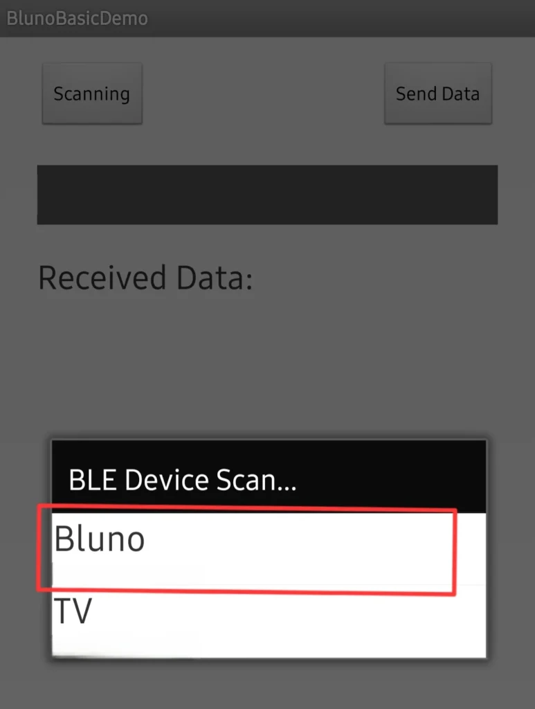
- Open the App: Launch the Bluno app and scan for nearby BLE devices.
- Select Bluno: Find and tap on Bluno in the list to connect.
- Send Commands: Use the app interface to send commands and control the board wirelessly.
Since BLE sends commands through serial communication, and our previous code was also based on serial inputs, we don’t need to make any changes to the code!
Simply connect the Bluno app to the RoMeo BLE board, and the same keyboard commands used in the Serial Monitor will now work over BLE.
This means you can control your robot wirelessly without modifying the existing code. Just pair your device, send the commands, and watch your robot move!
Finally…
Great! Now you have a fully functional Bluetooth-controlled robot using the RoMeo BLE board. Although the current setup works with a basic app, a custom-built app would provide better controls and an improved user experience. In the future, I’ll develop an app for it to enhance functionality.
I hope you enjoyed this tutorial! If you have any questions or doubts, feel free to leave a comment.