
Previously we learnt how to decode IR signals using Arduino and how to use these signals to control LEDs. It was a pretty basic setup and a good project to get started. Today we will use that knowledge to build a simple robot car which will be controlled using an IR remote. I suggest you check out “Everything you need to know about motor drivers” article to get a better understanding of how to control the motors.
Disclaimer: This blog contains Amazon and Banggood Affiliate links. Buying products from those links helps us run this blog without any extra charges on you.
Requirements:
For any projects, we need some materials. Here I have listed all the hardware and software requirements for this project.
Hardware:
- Arduino Uno (Amazon US / Banggood)
- Arduino Motor Shield v1.0 (Amazon US / Banggood)
- 2 x Geared Motor (Amazon US / Banggood)
- 2 x Wheels (Amazon US )
- Caster Wheel (Amazon US / Banggood)
- 2WD Chassis (Amazon US / Banggood)
- 1838 IR Receiver (Amazon US / Banggood)
- 3 x Female Headers (Amazon US / Banggood)
- 4 x 3.7v Li-ion batteries (Amazon US / Banggood)
- Li-ion Battery Holder (Amazon US / Banggood)
- LM2596 5v Voltage Regulator (Amazon US / Banggood)
- DC Power Jack (Amazon US / Banggood)
- IR Remote (Amazon US / Banggood)
Software:
- Arduino IDE: For writing and uploading code
- SketchUp: For designing Chassis
That’s all the things we need for this project, now let’s move on to the next step, designing a chassis.
Building Chassis:
Building a chassis is an optional part here, you can just skip this step and get yourself a 2WD robot chassis. I have built myself one using foam board, The design is pretty simple you can refer to this Sketchup file.
Making Circuit:
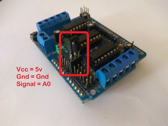
The circuit is pretty straightforward, The motor shield is placed on top of the Arduino board and the IR receiver is connected to the A0 pin. Refer to the following image.
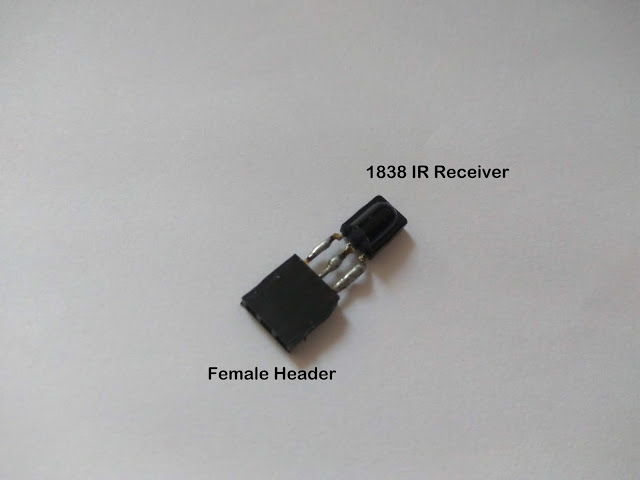
Here I have soldered the pins of the receiver directly to female headers. Which can be connected to the motor shield directly as shown below:
Note:- If you are not familiar with the 1838 IR receiver, check out this article.
Now about the power supply, we need two. One for Arduino (9-12V) and another for Motorshield (12-30V). For our motor requirements, we need at least 12V so we will use a 4cell 18650 battery pack. 4 x 3.7 will give us 14.5V which is enough for motor drive.
But now the problem is about Arduino, we cannot power the microcontroller with more than 12v. To solve this problem I have used a DC to DC voltage regulator. Check the power supply circuit diagram given below for better understanding.
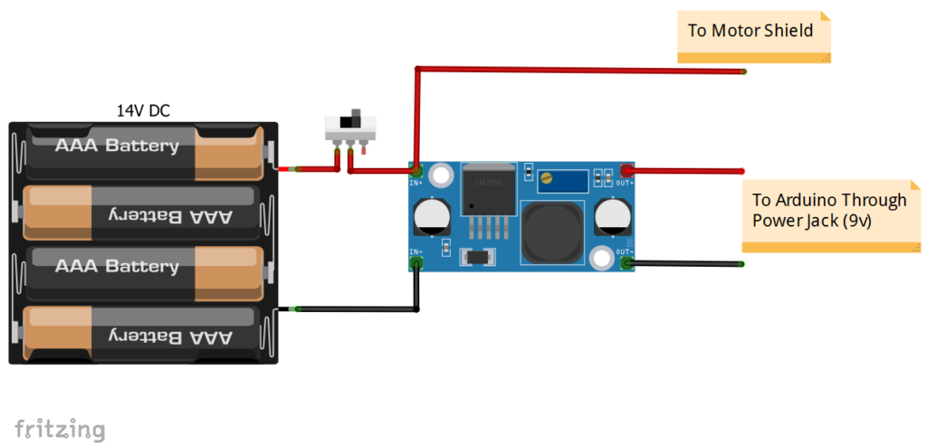
This is a pretty simple circuit and needs no further explanation. But before you connect the output to Arduino, use a multimeter to check if the voltage is between 9-12V. You can adjust the voltage by adjusting the screw on the trimmer.
Coding:
Now we can write the code to control our robot.
First, get any IR remote you wish to use and decode its IR signals. If you have no idea how to do that, check out this article.
Once you have successfully decoded the IR signals of the buttons on your remote, you should have some hex numbers such as: 20DF02FD, 20DFE01F, etc.
We will use these codes in the script below:
Note: Make sure that you have the “IRremote” and “AFMotor” libraries installed in IDE.
#include <IRremote.h>
#include <AFMotor.h>

int RECV_PIN = A0; //data out of IR receiver connects to pin A0
AF_DCMotor motor1(3);
AF_DCMotor motor2(4);

IRrecv irrecv(RECV_PIN);
decode_results results;

void setup()
{
 Serial.begin(9600);
 irrecv.enableIRIn(); // start the receiver
 motor1.setSpeed(100);
 motor2.setSpeed(100);
}

void loop()
{
 if (irrecv.decode(&results))
 {
   Serial.println(results.value, HEX);
   irrecv.resume(); // Receive the next value
   if (results.value==0x20DF02FD)
   { //Go Forward
     motor2.run(FORWARD);
     motor1.run(FORWARD);
     motor1.setSpeed(100);
     motor2.setSpeed(100);
   }

   if (results.value==0x20DF827D)
   { //Go Backward
     motor1.run(BACKWARD);
     motor2.run(BACKWARD);
     motor1.setSpeed(100);
     motor2.setSpeed(100);
   }

   if (results.value==0x20DFE01F)
   { //turn left
     motor1.run(FORWARD);
     motor2.run(BACKWARD);
     motor1.setSpeed(80);
     motor2.setSpeed(80);
   }

   if (results.value==0x20DF609F)
   { //turn right
     motor1.run(BACKWARD);
     motor2.run(FORWARD);
     motor1.setSpeed(80);
     motor2.setSpeed(80);
   }

   if (results.value==0x20DF22DD)
   { //stop
     motor1.run(RELEASE);
     motor2.run(RELEASE);
   }
 irrecv.resume();
 }
}
In the above codes just replace the codes with yours and make sure to put the ‘0x’ prefix.
Now you can power up the robot and start controlling it with your IR remote.
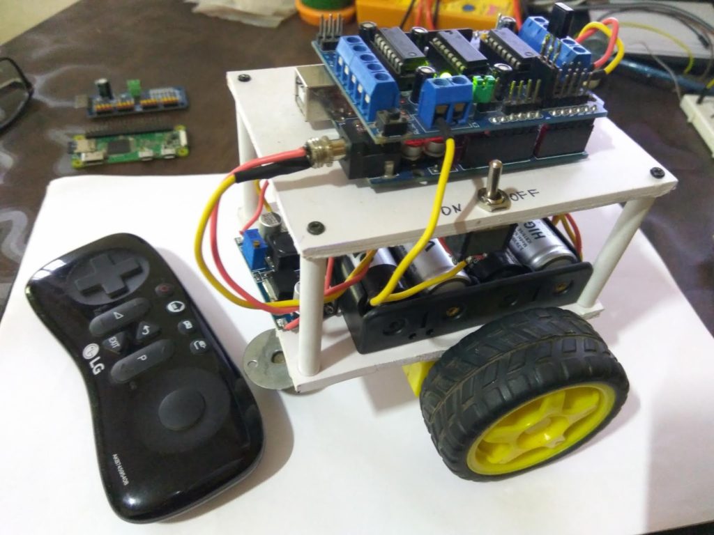
Final Note:
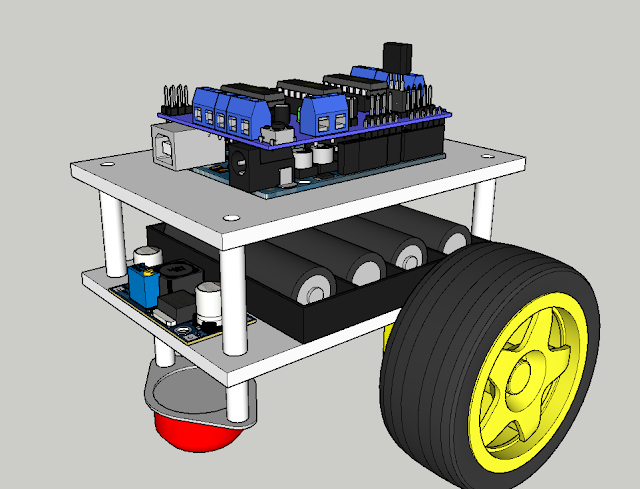
Here is a look at the robot I made, you can go ahead and make your own design.
Also, you might like to increase the speed of the robot, to do that just increase the number in the setSpeed() function. It can be anywhere between 0-255, where 0 will stop the motors completely and 255 will set the highest speed as per the motor.
With that being said, you can now make a robot and play around. If you have any questions or doubts, feel free to comment down below. If you find this informative and would like more of this content, please subscribe.
2 thoughts on “IR Controlled Robot Using Arduino!”
Thanks, I’ve been wanting to use my remotes and your code should help to do that.